Product:
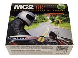
SportVue MC2
Product Type: Motorcycle Electronics
Manufacturer: Motion Research
URL:
http://www.sportvue.com
Product Rating: (Will be posted when testing is complete.)
Price: $389.00 - On Sale for
$299.00 until December 31, 2005
 Part 2 - Installing the SportVue MC2 System
First I would like to offer a few words of advise to those of you who decide to get a SportVue MC2 for yourselves. The owners manual that is provided does a good job of documenting the installation, configuration and operation of the SportVue. I suggest you look over the manual before you ever begin installing the hardware on your helmet and your bike. The process is not hard but I'm sure you will find the process quite a bit easier if you have a clear picture of what is involved before you get started. Once you have looked over the instructions I would suggest you go back and re-read each step as you go through the install. As long as you take your time you should not have any problem installing the SportVue yourself.
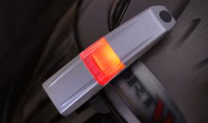
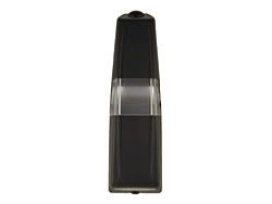
Before you begin the installation you need to find out which of your eyes is dominant. The SportVue is designed to work best when the Head Mounted Display or HMD is positioned above your dominant eye. The manual outlines a rather simple procedure you can complete in your home in a matter of minutes. Once you have determined your dominant eye you can begin the process of installing the HMD on your helmet. Two mounting clips are included with the kit. I selected the left eye mounting clip based on my left eye dominance. The two clips are very similar however one will fit the curvature of your helmet visor on the left and the other will fit the right side.
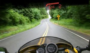
First you install the two AAA batteries that are provided with the kit into the Head Mounted Display or HMD. Next you place the HMD into the mounting clip you have selected. You're not ready to install anything permanently at this point. You'll just be testing the positioning of the HMD. In order to position the HMD you will need to sit on your motorcycle with your helmet on and adjust the HMD until it is properly in your field of view. Take your time with this step, make sure you get it aligned properly and be certain you're happy with the position before you move on. It's best if you have someone to help you with this and the next few steps. When you sit on your bike try to sit in a natural position for your riding style. Correct positioning will put the HMD unit just above your normal field of view while looking out at the road ahead. You should only have to barely glance upwards to see the display. When your finding the right position you will want to have the HMD powered on and you will want to make sure that the display is not cut off top to bottom or left to right. Making left to right adjustments is done by sliding the HMD along the top edge of your helmet visor. Top to bottom adjustments are made by using a tiny allen wrench that is provided with the kit. Be sure you keep the mounting clip pressed against the visor while your making adjustments. Once you think you have the HMD in the correct location check again to make sure that you are still sitting in a natural riding position before marking the final location. Once you have everything situated, carefully mark the location on your visor using a fine point permanent marker. Don't worry you won't be able to see that mark after you complete the next step. If you need to make minor top to bottom adjustments after you have attached the HMD mounting clip you will be able to do that so top to bottom placement is not as critical as left to right positioning.

Next you will need to prepare the surface of your helmet visor to attach the mounting clip. The kit comes with a sanding mask and some sandpaper to scuff the surface of your helmet visor in the location where the mounting clip will attach with adhesive pads. Scuffing the surface of the visor is required ensure the mounting clip will retain a firm attachment to the surface of the visor. Once you peel the adhesive backing off the sanding mask you can stick it to your visor in the position you previously marked with your marker. When you have the sanding mask in position I suggest you check to make sure that the mounting clip lines up correctly before you begin sanding. I ended up cutting the sanding mask in half to allow for easier positioning.
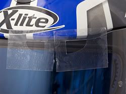
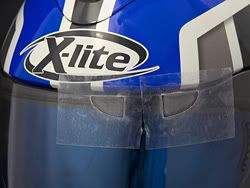
When the mask is in place and you have checked to make sure the mounting clip will line up you can begin sanding the visor surface. The sanding mask will prevent you from scuffing areas you didn't intend to sand but still use caution while you sand. Once you have sanded the entire area in the openings of the sanding mask you will need to clean the surface of the visor with one of the supplied alcohol pads. Finally remove the sanding mask and install the mounting clip according to the instructions.
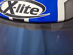
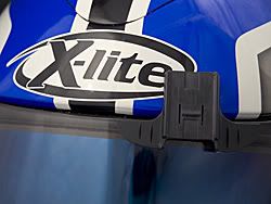
When the clip is mounted to your visor, place the Head Mounted Display back in the clip and place your helmet back on your head and re-check the positioning. If you need to make any adjustments do them now. When your satisfied put your helmet on the shelf for 24 hours to allow the pressure sensitive adhesive on the mounting clip to properly bond to your visor. Let's face it you don't want your heads-up display flying off when breezing down the highway.
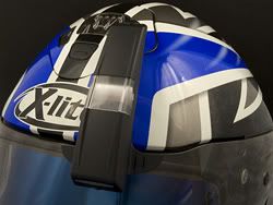
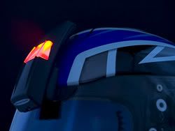
Now that you have the Head Mounted Display behind you it's time to begin installing the Motorcycle Sending Unit or MSU on your bike. Before you begin this part of the process jump on your computer and head over to the SportVue website at
www.sportvue.com and take a look at the motorcycle instruction database Motion Research has provided. You will find a number of late model bikes broken down by make and model. If your bike is listed you will be able to download and print out a supplemental guide with specific instructions on installing the MSU on your bike. I currently ride a 2005 Yamaha FJR 1300 ABS and I found the extra instructions quite helpful.
Before you begin installing the MSU you will need to find a suitable mounting location. The instruction manual recommends a location inside a fairing, under the seat or near the rear of the motorcycle. I found the location recommended by the guide supplement online to be a prefect fit for my installation, under the passenger seat and near the rear of the motorcycle. The FJR even has a rubber tie-down strap that I was able to use to secure the MSU in place. It was almost as if the MSU was made to fit in this location. If your bike is something other than the Yamaha FJR the kit includes both tie-wraps and a patch of Velcro to secure the MSU.
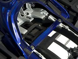
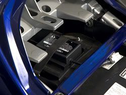
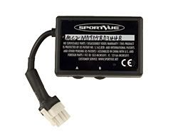
Once the Motorcycle Sending Unit is in place it's time to attach the wiring harness by plugging it into the MSU. The wiring harness has four wires, a wheel speed sensor cable, a red 12 volt power lead, a black 12 volt ground lead, and a black coaxial wire for the RPM signal input. The kit also includes an assortment of connectors and accessories allowing you to achieve a clean professional looking installation.
The first wire to route is the wheel speed sensor. The owners manual strongly suggests you mount the wheel speed sensor to the rear wheel. I was able to find a suitable location on my rear wheel with no problem. Routing the wire and keeping it hidden meant that I needed to remove a few pieces of plastic from my bike first. This task was accomplished without too much trouble.
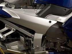
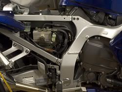
When you have the cable and the sensor routed to your rear wheel you will need to select one of the mounting brackets included with the kit to mount the wheel sensor close to the rear wheel. I used a bracket with two 90 degree right angles. I took some extra time with the bracket and drilled another hole in the bracket where it would mount to a bolt that holds the ABS sensor for my rear wheel in place. I would have been able to install the sensor without this step but I wanted to place the bracket a little lower and closer to the support. This also allowed for a little bit better placement of the magnet on the rear wheel hub on my bike.
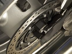
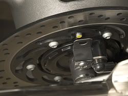
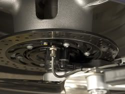
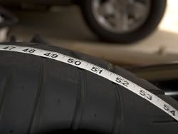
Once you have the sensor bracket installed you'll want to place the sensor in the bracket and then temporarily attach the magnet to the wheel. The magnet that is provided quite strong for it's size but you will still need to use the included epoxy to permanently attach the magnet to the wheel. The speed sensor is able to determine the speed of your motorcycle by counting the each time the magnet mounted to the wheel passes by the sensor. Later you will input the circumference of your rear tire allowing the MSU to properly calculate your speed. When you position the speed sensor and the magnet you need to make sure they pass within 1/4 inch of each other so here again take your time and make sure everything is lined up before making things permanent.
When you have the sensor in place and the magnet located, rotate the rear wheel around a few times by hand to make sure the magnet and the sensor will not come in contact with any moving parts on your wheel.
If it's not evident to you by now let me point out that you will need some means of getting your rear wheel off the ground in order to install this product. If your bike does not have a center stand you will need a service or paddock stand to support your bike and lift the rear wheel off the ground. Let me also point out that if you think you can get by without it, think again. You will need that rear wheel off the ground again later.
Next use the included epoxy to attach the magnet to the wheel according to the instruction manual. After the epoxy has begun to set you can secure the speed sensor by applying the included thread lock and tightening the jam nuts. If you find that your speed sensor can not be mounted in the typical location the instruction manual covers many alternate locations that may work better for your motorcycle.
Next up is the RPM wire tap. Hang in there, we're almost done. The RPM wire tap needs to be located on your motorcycle's camshaft or crankshaft sensor. Older motorcycles may need a spark plug pickup wire accessory available from the SportVue website. On the FJR I was able to tap into the RPM sensor wire at the ECU. The supplemental guide I downloaded from the SportVue website included the information I needed to locate this wire with ease. Bravo to Motion Research for providing this information. Getting to my ECU wiring harness again required that I remove some plastic body panels from my bike. Once I gained access I tapped into the wire with one of the high quality wire taps included with the kit.
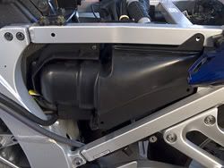
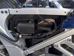
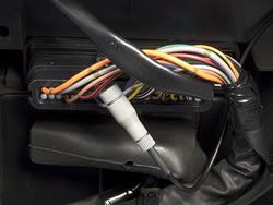
Okay, I promised we were almost done and this is it. We're down to the final step for installation, hooking up the power and ground wires for the MSU. You will need to locate a suitable power and ground wire in your bikes electrical system that is switched by your bikes ignition. I am planning to add a secondary fuse panel to my motorcycle and that is where I will ultimately connect the power and ground wires for the SportVue MSU but for now I just tapped into the tail lamp wiring as suggested in the supplemental manual I downloaded from the SportVue website.
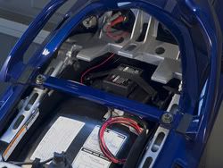
Now that you have all the parts installed and the wires routed make sure you go back and tidy up any loose wiring using the provided wire ties. Pay extra attention to the cable for the speed sensor, you wouldn't want the cable to come loose and get tangled up in your rear wheel. For me this step also included the reattachment of those few body panels that I removed earlier.
I hope you enjoyed this somewhat exhaustive look at how the SportVue MC2 kit is installed. If it seems overwhelming to you, don't worry. As I said before the manual that is provided with the kit is detailed and easy to understand. Take your time and be patient and if you get stuck Motion Research offers technical support to help you with any questions you might have. I also like to remind you that information I have provided here is by no means a substitute to reading the owners manual provided with the kit.
Up next I'll cover the configuration and operation of the SportVue MC2 and share with you some of my thoughts about the product.
Note: Most of the images in this review are linked to larger photos.
